


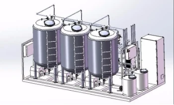


Clean-In-Place System CIP Tank
The Clean-In-Place System CIP Tank is designed to prepare, heat, hold and recover cleaning solutions for process equipment and pipelines without dismantling them. The configuration is selected according to the cleaning stages, solution volume, target temperature, circulation flow and return requirements.
Technical Specifications
|
Parameter |
Reference / Configuration |
|
Tank Capacity |
200–8,000 L |
|
Product-Contact Material |
SS304 / SS316L |
|
Heating Method |
Steam / electric / hot-water heating, according to process requirements |
|
Operating Temperature |
According to cleaning process; 60–90°C is typical for many hot-cleaning applications |
|
Design Temperature |
According to final equipment design |
|
Tank Connection |
DN32–DN50 for reference models; customized sizes available |
|
Surface Finish |
According to sanitary and process requirements |
|
Insulation |
According to operating temperature and heat-loss requirements |
|
Temperature Measurement |
RTD / PT100 sensor |
|
Level Measurement |
Level switch / level transmitter |
|
CIP Return Connection |
Customized according to circulation flow and system layout |
|
Tank Drain |
According to tank capacity and drain requirements |
|
Tank Dimensions |
See dimensional reference table |
Dimensional Reference Table
|
Capacity (L) |
H1 (mm) |
H2 (mm) |
H3 (mm) |
H (mm) |
DN (mm) |
|
200 |
400 |
800 |
235 |
1085 |
32 |
|
250 |
400 |
850 |
235 |
1135 |
32 |
|
300 |
460 |
910 |
235 |
1195 |
32 |
|
500 |
640 |
1140 |
270 |
1460 |
40 |
|
600 |
830 |
1130 |
270 |
1450 |
40 |
|
800 |
880 |
1430 |
270 |
1750 |
40 |
|
1000 |
880 |
1480 |
270 |
1800 |
40 |
|
1200 |
1100 |
1700 |
270 |
2020 |
40 |
|
1500 |
1150 |
1800 |
270 |
2120 |
40 |
|
2000 |
1220 |
1970 |
280 |
2300 |
40 |
|
2500 |
1150 |
1980 |
280 |
2310 |
40 |
|
3000 |
1220 |
2120 |
280 |
2450 |
40 |
|
4000 |
1250 |
2250 |
280 |
2580 |
40 |
|
5000 |
1500 |
2550 |
320 |
2950 |
50 |
|
7000 |
1450 |
2650 |
320 |
3050 |
50 |
|
8000 |
1750 |
2950 |
320 |
3350 |
5 |
These dimensions are reference values. Final dimensions, nozzle positions and connection sizes are confirmed according to the selected capacity and CIP system layout.
CIP System Configuration by Cleaning Cycle
A typical cleaning sequence can be arranged as:
Cleaning Solution Preparation → Heating → Circulation → Return → Recovery / Discharge → Next Cleaning Stage
The number of tanks, pumps, valves and return lines is determined by the cleaning stages, circuit volume, solution reuse requirements and return arrangement.
Cleaning Solution Configuration
|
Cleaning Requirement |
Typical Tank Arrangement |
Main Purpose |
|
Alkaline cleaning |
Alkali solution tank |
Removes organic residues and process deposits |
|
Acid cleaning |
Acid solution tank |
Removes mineral deposits and scale |
|
Hot-water rinsing |
Hot-water tank |
Rinses the cleaning circuit |
|
Solution recovery |
Return / recovery tank |
Collects solution for reuse or further treatment |
|
Disinfection |
Disinfectant solution tank |
Supports the specified disinfection stage |
Key CIP System Configuration Factors
Tank material and configuration should match the cleaning solution and required cleaning stages.
Heating capacity is selected according to solution volume, target temperature, heating time and heat loss.
Pump capacity, pipe diameter, valves and return piping should match the required cleaning flow.
The tank can be configured for solution reuse, recovery or discharge according to the cleaning procedure.
CIP Monitoring & Instrumentation
Temperature - Monitors cleaning solution temperature during the cleaning cycle.
Flow - Monitors circulation through the selected equipment or pipeline circuit.
Conductivity - Helps monitor solution concentration and distinguish cleaning and rinsing stages.
Level - Monitors tank liquid level and supports filling, transfer or low-level protection where required.
Information Required for Quotation
|
Item |
Information Required |
|
Cleaning Circuit |
Equipment and pipeline volume |
|
Cleaning Solutions |
Solution types and cleaning stages |
|
Temperature |
Target temperature and heating time |
|
Circulation |
Required flow rate and circuit arrangement |
|
Connections |
Existing pipe sizes and connection standards |
|
Installation |
Available space and existing connection conditions |
CIP Tank vs Complete CIP System
CIP Tank: The tank serves as the solution preparation, heating, holding and/or recovery vessel within a CIP system. It can be supplied as an individual tank for integration with an existing CIP circuit.
Complete CIP System: A complete CIP system may include tanks, circulation pumps, heat exchangers or heaters, valves, pipelines, instruments and a control system. The configuration depends on the number of cleaning stages and required operating sequence.
Manufacturing & Integration
CIP tanks can be manufactured according to specified capacity, material, heating method, connection size and instrumentation requirements.
Manufacturing considerations may include:
- Tank fabrication and welding
- Product-contact material selection
- Nozzle and connection fabrication
- Internal surface finishing
- Dimensional inspection
- Leak or pressure testing where applicable
- Final connection and component inspection
For complete CIP projects, the tank can be coordinated with pumps, valves, pipelines, heat exchangers and control components according to the required cleaning circuit.
Before fabrication, key information such as tank capacity, cleaning flow, heating duty, connection requirements and installation space should be confirmed.
FAQ
Q: What tank capacity should be selected for a CIP system?
A: The required capacity depends on the cleaning circuit volume, operating level, solution retention and return requirements. Connected equipment and pipelines should be considered when determining the total solution volume.
Q: Can the CIP tank be customized for an existing production line?
A: Yes. Tank dimensions, connection sizes, nozzle positions and instrumentation can be adapted to existing equipment and available installation conditions.
Q: What material can be used for the CIP tank?
A: Stainless steel is commonly used for CIP tanks. SS304 or SS316L can be selected according to the cleaning solution, corrosion requirements and operating conditions. Surface finish can also be specified for the application.
Q: Can one CIP tank be used for multiple cleaning stages?
A: It depends on the cleaning procedure and solution requirements. Separate tanks may be required when different cleaning solutions need to remain separated, while some systems can use one tank for sequential cleaning stages.
Q: What information is required to select a CIP tank?
A: Key information includes tank capacity, cleaning solution types, cleaning stages, target temperature, heating time, circulation flow, connected equipment volume, connection requirements and available installation space.
Q: Can the CIP tank be supplied as part of a complete CIP system?
A: Yes. The tank can be integrated with pumps, valves, pipelines, heating components, instruments and controls according to the required cleaning circuit and operating sequence.
Hot Tags: clean-in-place system cip tank, China clean-in-place system cip tank manufacturers, suppliers, factory, cip, Clean In Place System CIP Tank
Send Inquiry
